![]()
stepper motor basics

Stepper Motor Basics
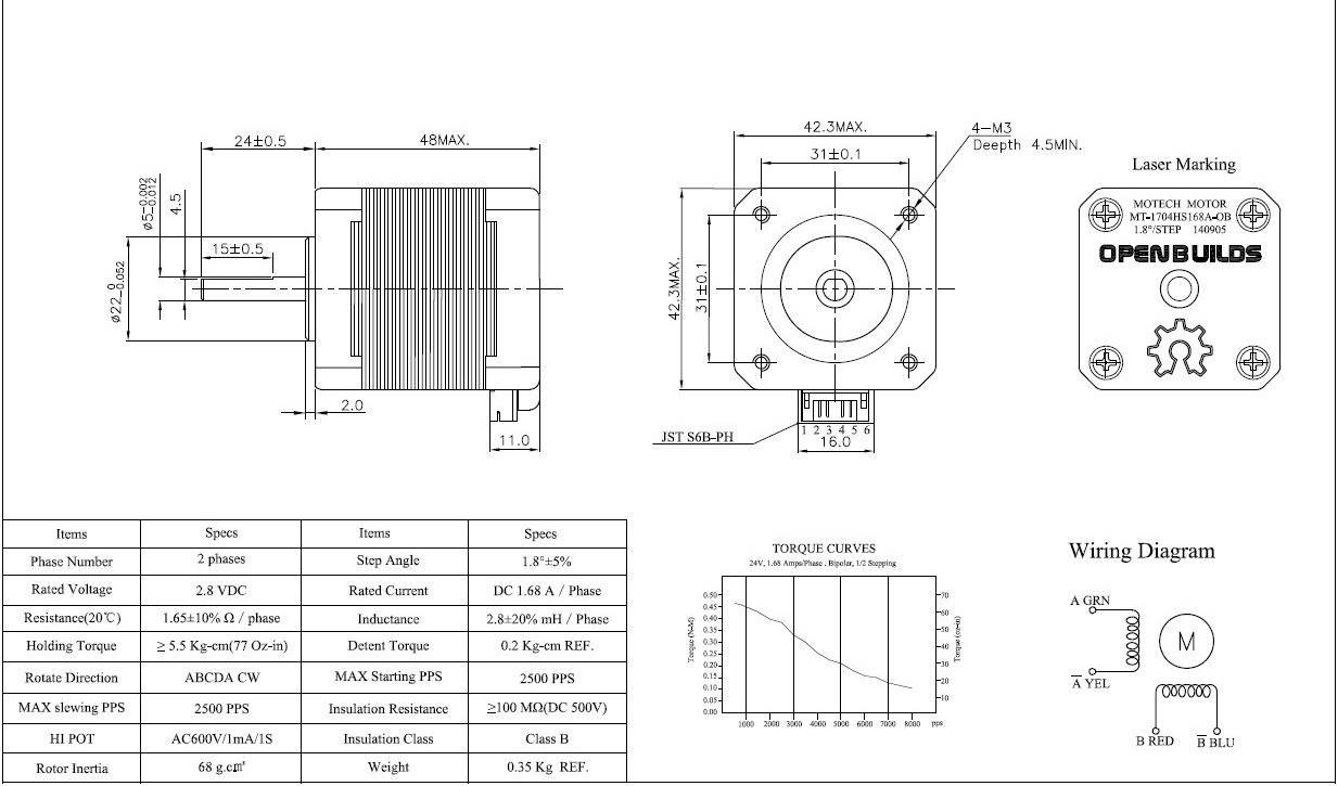
A stepper motor is a brushless, synchronous electric motor that converts digital pulses into mechanical shaft rotations. Each rotation of a stepper motor is divided into a set number of steps, sometimes as many as 200 steps. The stepper motor must be sent a separate pulse for each step. The stepper motor can only receive one pulse and take one step at a time and each step must be the same length. Since each pulse results in the motor rotating a precise angle — typically 1.8 degrees — you can precisely control the position of the stepper motor without any feedback mechanism.
As the digital pulses from the controller increase in frequency, the stepping movement converts into a continuous rotation with the velocity of the rotation directly proportional to the frequency of the control pulses. Stepper motors are widely used because of their low cost, high reliability, and high torque at low speeds. Their rugged construction enables you to use stepper motors in a wide environmental range.
Advantages of Using Stepper Motors
- A wide range of rotational speeds can be utilized since the speed of a step motor is proportional to the frequency of the input pulses from your controller.
- Precise open-loop positional control is possible with a stepper motor without any feedback mechanism.
- Very low speed rotation is possible with a load that is coupled directly to the shaft of the stepper motor.
- A stepper motor is quite reliable because there are no contact brushes. Generally, the life of a stepper motor is determined by the life of the stepper motor bearing.
- A stepper motor is very good at starting, stopping, and reversing direction.
- A stepper motor provides precise positioning and repeatability of movement.
- An energized stepper motor maintains full torque at standstill position.
Types of Stepper Motors
There are three kinds of step motors: permanent magnet, hybrid, and variable reluctance. Hyrbrid step motors offer the most versatility and combine the best characteristics of variable reluctance and permanent magnet stepper motors. Hybrid stepper motors are constructed with multi-toothed stator poles and a permanent magnet rotor. A standard hybrid stepper motor has 200 rotor teeth and rotates 1.8 degrees per step. Hybrid stepper motors provide high static and dynamic torque and they run at very high step rates. Applications for hybrid stepper motors include computer disk drives and cd players. Hybrid stepper motors are also widely used in industrial and scientific applications. Hybrid step motors are used in robotics, motion control, automated wire cutting, and even in high-speed fluid dispensers.
Step Modes
Stepper motor “step modes” include full step, half step, and microstep. The type of step is dependent on the stepper motor driver controlling the stepper motor. Many stepper motor controllers are multi-step capable (usually adjusted by switch setting).
Full Step
Standard hybrid stepping motors have 200 full steps per revolution. If you divide the 200 steps into the 360 degrees of rotation you get 200 1.8 degree steps. Normally this is achieved by energizing both windings while alternately reversing the current, meaning one pulse from the driver is equal to one full step on the step motor.
Half Step
Half Step means that the stepping motor is rotating at 400 steps per revolution (0.9 degree steps x 400 = 360 degrees). First one winding is energized and then two windings are alternately energized. This will cause the rotor of the stepping motor to move at half the distance (0.9 degrees). In half-step mode, a typical stepper motor provides about 30% less torque, but it provides a smoother motion than it would in full-step mode.
Microstep
Microstepping is a relatively new stepping motor system. Microstepping energizes the stepper motor winding in a manner that further subdivides the number of positions between poles. Some microstepping controllers are capable of dividing a full step (1.8 deg) into 256 microsteps. This would result in 51,200 steps in one revolution (.007 deg/step). Microstepping is usually applied to applications that require accurate positioning and smoother motion over a broad range of speeds. As in the half-step mode, microstepping reduces torque by about 30% compared to full-step mode.
Linear Motion Control
Stepping motors are often used for linear motion control using a lead screw or worm gear drive. The pitch of the lead screw controls the amount of linear distance traveled in one revolution of the screw. So, if the lead is equal to one inch per revolution and there are 200 full steps in one revolution of the stepping motor shaft, then the resolution of the lead screw system would be 0.005 inches per step. Finer resolutions can be attained using the step motor and stepping motor driver combination in microstep mode.
Series and Parallel Connection
A stepper motor can be connected either in series or parallel mode. A series connection system results in high inductance and consequently greater torque at low speeds. A parallel connection method will reduce the inductance resulting in increased torque at higher speeds
Stepper Motor Drivers Overview
The stepper motor is controlled by a stepper motor driver board. The stepper motor driver receives step and direction signals from a control system, typically a computer, and converts them into electronic signals which run the stepper motor. One pulse is needed for every step of the stepper motor shaft. In full-step mode, assuming you’re using a standard 200 step motor, 200 steps or pulses completes one revolution of the stepping motor shaft. The speed and rotation of the stepper motor shaft is directly proportional to the frequency of the pulse.
The speed and torque of a stepper motor is determined by the flow of current from the stepping motor driver to the stepping motor winding. Inductance reduces the flow or limits the time it takes for the current to energize the winding. Most stepper motor driver circuits are designed to supply a greater amount of voltage than the stepper motor’s rated voltage. The higher the output voltage from the stepper motor driver, the higher the level of torque versus speed. In general, the stepper motor driver’s output voltage, also known as bus voltage, should be rated five to ten times higher than the stepper motor’s voltage rating. In order to protect the stepping motor, the step motor controller’s current should be limited to the step motor current rating.
Controller (Indexer) Overview
The stepper motor controller, also known as an indexer, provides step and direction outputs to the stepping motor driver. Most applications require that the controller manages other functions as well such as acceleration, deceleration, steps per second, and distance. The controller (indexer) can also connect to and control other external signals as defined by the project.
Communications to the stepping motor system indexer is usually provided through an RS-232 or RS-485 port. In either configuration, the indexer can receive high level commands from a host computer and supply the appropriate step and direction pulses to the stepper motor driver.
The stepping motor system indexer includes auxiliary input/output for monitoring from external sources such as Go, Home, Jog, or Limit switch.